There are two project types:
See Creating the Main Hardware Project
A hardware project contains the customizable resources of the programmable FPGA of an M3xxxA hardware module. When selecting a target module, the project is opened with the factory settings of a standard module. The custom on-board solution is developed within this hardware project and is saved, compiled and loaded into the hardware module (the binary can be loaded into multiple identical modules). As per Figure 3, part of the hardware project can be made up of FPGA user block projects, which are created as follows.
See Creating an FPGA Block Project
The purpose of an FPGA Block project is to create independent user FPGA blocks. They can be designed to provide custom functionality to other projects. These blocks once created, can be saved and reused in other hardware projects, and in other FPGA Block projects as shown in Figure 3.
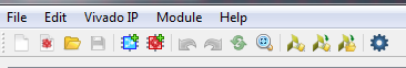
When a Hardware Project or FPGA Block editor window is launched, the following GUI choices are available. See tables 1 and 2 for more information.
| Menu Item | Description (see Table 2 for Icon numbers) |
|---|---|
| File | Includes Menu Icons 1 - 6 and Save As ..., Recent Project, Close, Settings, and Exit |
| Edit | Includes Menu Icons 7 - 8, and Select All |
| Vivado IP | Includes Menu Icons 11, 12, and 13 |
| Module | Enables assigning hardware, generating, and loading firmware |
| Help | License Management... and About... |
Table:1
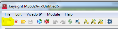
| Icon | Description | |
|---|---|---|
| 1 |

|
Creates a new hardware project |
| 2 |

|
Creates a new FPGA Block |
| 3 |

|
Open a file, such as a project file |
| 4 |

|
Saves a project file |
| 5 |

|
Adds an External Block |
| 6 |

|
Adds an FPGA Block |
| 7 |

|
Undoes changes |
| 8 |

|
Redoes changes |
| 9 |

|
Redraw Connections |
| 10 |

|
Fit In Window |
| 11 |

|
Launches the Vivado Tool |
| 12 |

|
Imports Vivado IPs |
| 13 |

|
Imports Vivado IP Locations |
| 14 |

|
Generates firmware |
Table: 2
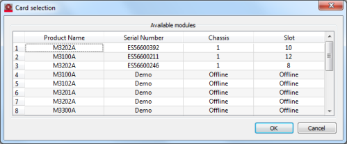
As per section 1.2.1 a hardware project contains the customizable resources of the programmable FPGA of an M3xxxA hardware module. When created, the project can be edited, saved, compiled and loaded into the hardware module (the binary can be loaded into multiple identical modules). These are the steps to create a hardware project:

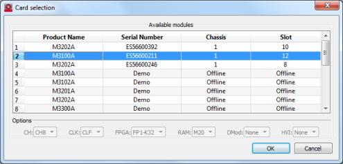
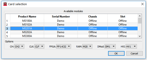

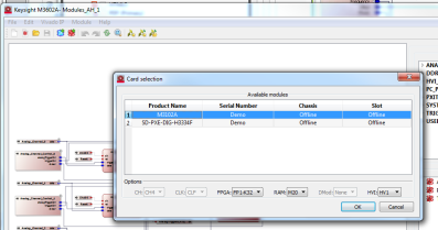
| Option | Description |
|---|---|
| CH: | Select the number of channels: for example, CH4 or CH8 |
| CLK: | Select the clock: CLF or CLV |
| FPGA: | Select the FPGA, for example, FP1-K32 or FP1-K41 |
| RAM: | Select the RAM, for example, M20, |
| DMod: | Select the DMod, for example, DM1 or None |
| HVI | Select the HVI, for example, HV1 or None |
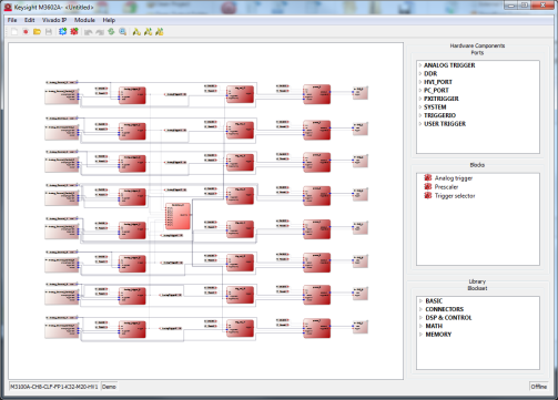
Review the default hardware configuration. Default functionality for each hardware module comes with ports, blocks and their connections. The default configuration can be edited for additional processing functions. See Editing Actions
When a project has been created, it can be saved. Once saved, it can be reloaded later to make further changes to it. The associated hardware and its firmware can be managed within a hardware project.
As can be seen in the following image, there are three selections in the Module menu drop-down to manage the project work flow:
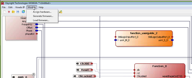
Select Module > Assign Hardware...
Before hardware can be assigned, the project needs to be saved.
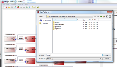
Click Save
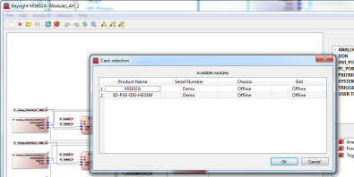
Select the module to assign the software project to.
Click OK to assign the selected module to the project.
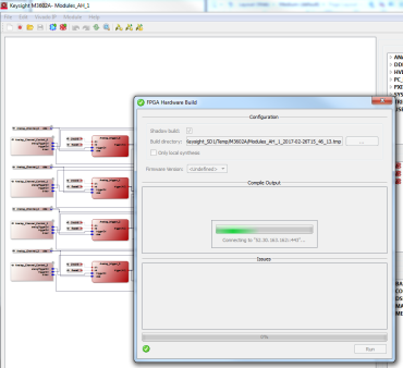
Select Module > Generate Firmware...
The M3602A software will connect to the cloud server, and start the firmware generation process. If the generation finishes successfully, the firmware file will be created inside the project folder. For more information and details, please see Generating FPGA Bitstream
Select Module > Load Firmware...
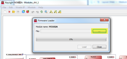
Select the "..." button highlighted above and navigate to the firmware file to be loaded.
Once selected, click the Load button to load the firmware into the hardware module.
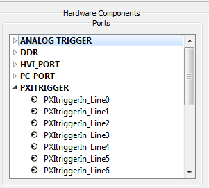
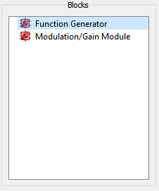
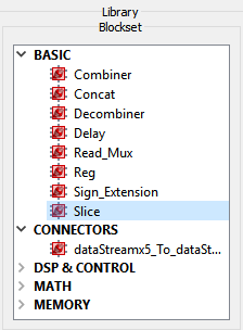
Much of the hardware project will be created by combining components from the three sections displayed on the right side of the GUI. These are divided into Hardware components and Library components.
In addition to these components, IP blocks can be brought in from the following sources: